

A motorcycle wiring diagram is a visual schematic that shows the electrical system arrangement on a motorcycle, starting from the battery to various other electronic devices. Learn what a motorcycle wiring diagram is and how to read it accurately.
Key Takeaways
- A motorcycle electrical wiring diagram shows how electrical components are interconnected and how power flows through the electrical system.
- Understanding wiring diagrams makes the process of installation and maintenance as well as troubleshooting safe and efficient.
- Correct identification and tracing of electrical parts and circuits are attributed to the use of wire color codes and electrical components diagrams.
- Following electrical diagrams for troubleshooting and installation helps avoid short circuits and damage of components.
- The reliability of motorcycle electrical systems, such as checking grounds and securing wires, improves with more knowledge and experience.
A motorcycle electrical wiring diagram is a schematic or visual guide that shows how the components and circuits on a motorcycle are connected. A good understanding of this diagram will help users and mechanics during repairs or maintenance. Additionally, if an electrical problem occurs, the wiring diagram will help diagnose the problem in more detail, quickly, and accurately. This is because wiring diagrams play an important role in ensuring that a motorcycle’s electrical system functions properly and efficiently. In this article, we'll take an extensive look at motorcycle wiring diagrams, from the definition, main components, how to read, step-by-step installation guide, how to troubleshoot, to practical tips.
What is a Motorcycle Electrical Wiring Diagram?
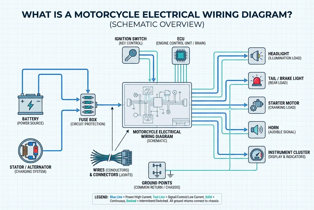
Motorcycle electrical wiring diagram is a schematic that shows the arrangement or relationship of every electrical system on a motorcycle. This diagram serves as a guide on how the electric current from the power source–usually the battery–flows to the various other electrical components on the motorcycle. Each cable or connection is displayed in a specific symbol or color to make it easy to understand. This diagram helps the user to understand each electrical system connection, starting from the cable path, fuse position, to the relationship between each electrical component. Thus, the repair process, checking, and replacing electrical components will take place more safely and avoid the risk of damage or short circuiting. This diagram is also useful when adding accessories or making electrical modifications safely.
Main Components in a Motorcycle Electrical Wiring Diagram
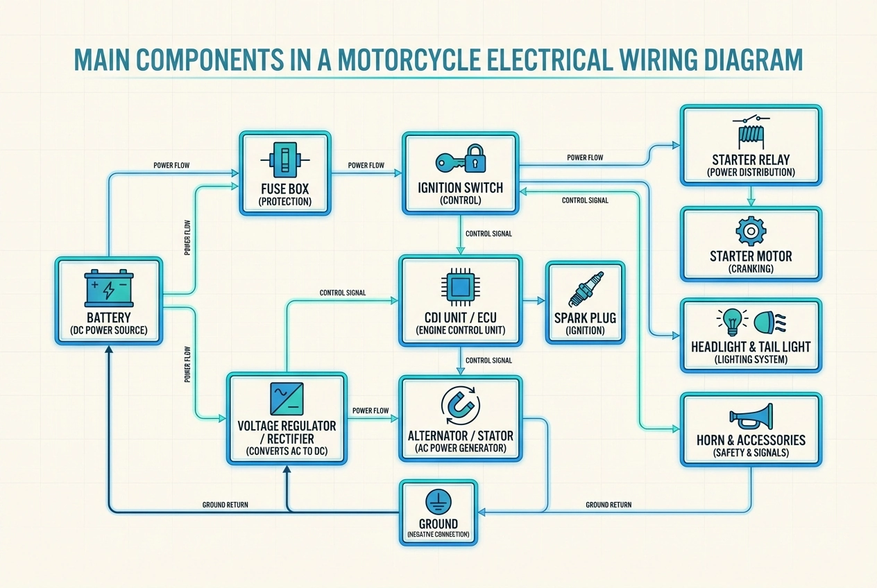
Generally, a motorcycle electrical wiring diagram shows the main components arranged within the motorcycle’s electrical system. Battery: The main source that provides the electrical energy to turn the electric motor. In wiring diagrams, this component is often the main point of power distribution to the entire electrical system. Battery Management System (BMS): Has the main function to organize or protect the battery from various electrical problems. In the wiring diagram itself, this component is often shown connected to the battery, charger, and controller. Controller: This component acts as the control unit of the electric motorcycle drive system, regulating how much current flows from the battery to the electric motor based on throttle input. In the wiring diagram itself, the controller is usually connected to the battery, electric motor, throttle, and various safety sensors. Electric Motor: Is a component that converts electrical energy into motion (mechanical) to make the wheels move. In the wiring diagram itself, this component is usually illustrated with thick cable lines and is directly connected to the controller. Throttle: A component that regulates how fast the motorcycle goes by sending a signal directly to the controller. In wiring diagrams, this component is often shown as a control input directly connected to the controller via a low-voltage signal cable. DC-DC Converter: Serves to reduce the high voltage from the main battery for some electrical systems such as lights, horns, and instrument panels with 12V specifications. In wiring diagrams, this component's image is generally very clear considering its crucial function. Charging System (On-board Charger and Charging Port): In the wiring diagram itself, this component is often shown in relation to the external power source, charger, BMS, and battery pack. Main Fuse and Circuit Breaker: This component aims to protect each component from electrical problems, so in the diagram it's usually on the main line between the battery and the controller. Control Units and Safety Switches: Are safety sensors that affect the controller's performance and also the electric motor in the wiring diagram.
How to Read Motorcycle Electrical Wiring Diagram?
To understand and read electrical wiring diagrams precisely and correctly, a systematic approach is needed. This is because electrical wiring diagrams use symbols and color codes to represent components and wiring paths. Here are some ways to recognize and read motorcycle wiring diagrams accurately.
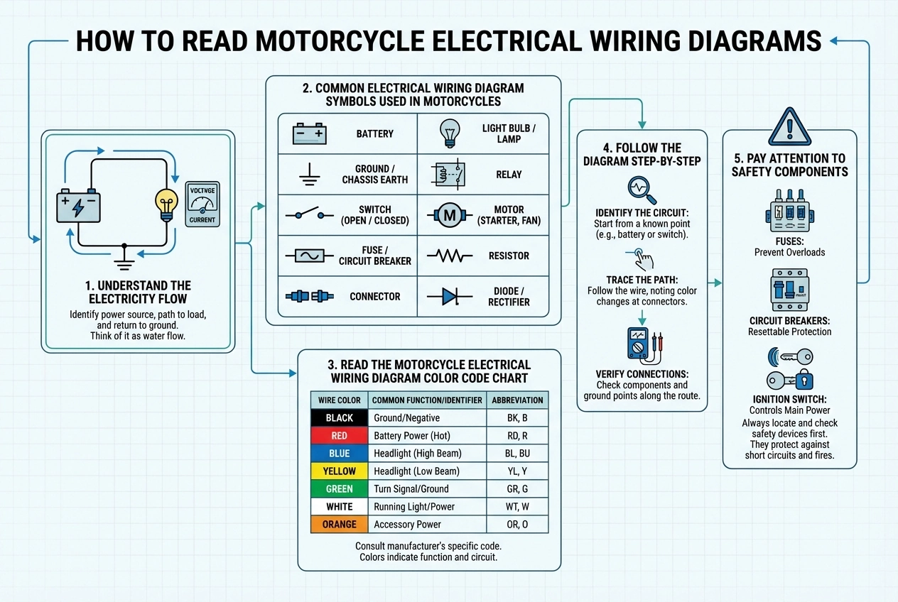
Understand the Electricity Flow
To properly read a wiring diagram, the first step is to understand the electricity flow direction. On an electric motorcycle, the electricity flow usually goes from the battery to the fuse, then to the controller or switch, and finally to various other components such as the electric motor, lights, or instrument panel. When a problem occurs, understanding the electrical current direction is essential to know where the main fault is.
Common Electrical Wiring Diagram Symbols Used in Motorcycles
Wiring diagrams generally only use special standard symbols to provide simple visualization. Here are some symbol charts that are commonly used in motorcycle electrical wiring diagrams.
| Symbol | Component | Description |
|---|---|---|
| 🔋 | Battery | The main power source that provides electrical energy to the motorcycle. |
| ⎓ | DC Power | Indicates direct current (DC) |
| ⏚ | Ground | Mass or negative line |
| ──///── | Fuse | Component that protects the electrical system from overcurrent |
| ⎍ | Switch | Current controller or ON/ OFF switch |
| ⚡ | Motor | Indicates an electric motor |
| ⧈ | Controller | Components that regulate the power flow from the battery to the electric motor |
| 💡 | Lamp | Components that function as a lighting system |
Read the Motorcycle Electrical Wiring Diagram Color Code Chart
Besides being equipped with special symbols, wiring diagrams also consist of various cable colors that are used to quickly identify cable functions. Here are some common color code charts that are often found.
| Wire Color | Function |
|---|---|
| Red | Power supply/ positive current flowing from the battery |
| Black | Ground/ negative current |
| Yellow | Lightning circuit |
| Blue | High beam or auxiliary lighting system |
| Green | Sensor or ground signal |
| White | Ignition or charging circuit |
| Orange | Control signal/ accessories |
| Brown | Tail light or running light |
Follow the Diagram Step-by-Step
When reading a wiring diagram, ensure that you focus on one system first–such as the charging system or the electric motor drive. Then, match each symbol with a physical component on the motorcycle, and follow the wiring path according to the colors and connectors shown on the diagram.
Pay Attention to Safety Components
Generally, some safety components such as fuse, circuit breaker, or relay are placed on the main line. If a problem occurs with the motorcycle's electrical system, understanding the wiring diagram helps identify which components may be damaged.
Step-by-Step: Motorcycle Electrical Wiring Diagram Installation Guide
When repairs or maintenance is performed, re-installing the wiring according to the wiring diagram is very important to ensure that each cable and component is installed according to its path. Therefore, here are some step-by-step guidance to follow the wiring diagram correctly.
Step 1: Prepare Tools and the Correct Wiring Diagram
Ensure that you have the appropriate wiring diagram and have prepared all the tools or materials needed. Tools that are generally needed are screwdrivers, pliers, multimeters, cable insulation, and cable ties.
Step 2: Disconnect the Power Source
Disconnect the battery to avoid any electric current flowing during the installation process.
Step 3: Identify the Main Circuits on the Wiring Diagram
Ensure that you understand the wiring diagram and mark the main lines from the battery, fuse, controller, motor, to the lighting system. By following this step, you'll understand the installation flow more easily before finally connecting the cables.
Step 4: Install the Main Power Wiring
In the installation process, ensure to start from the main line–i.e. from the battery to the fuse and controller. Then, ensure that the cables are sized according to the specifications and the connections are firmly in place.
Step 5: Connect Control and Signal Wires
Connect each control cable to the motorcycle's internal components according to the symbols and color codes on the wiring diagram.
Step 6: Install Auxiliary Systems
Ensure that supporting electronic systems such as lights, DC-DC converter, horn, and charger port are connected to the right path and protected by a fuse or circuit breaker.
Step 7: Secure and Organize the Wiring
Once all connections are made, tidy up the wiring using cable ties and ensure that no wires are pinched, kinked, or close to hot components. Proper cable organization will help make maintenance easier and maintain safety.
Step 8: Check Connections and Reconnect the Battery to Test the System
Ensure that all connections are tightly, neatly, and in accordance with the wiring diagram. Then, reconnect the electrical system with the battery to confirm that everything is working optimally.
How to Troubleshoot Issues with Motorcycle Electrical Wiring Diagram?
Electrical wiring diagrams are often used to help solve problems that occur in electrical systems that are difficult to detect. With a good understanding of wiring diagrams, this allows issues to be traced logically and efficiently. Here are some ways to troubleshoot. Identify the Problem Symptoms: Identify the fault symptoms, then match the symptoms with the relevant system on the wiring diagram. Locate the Related Circuit on the Wiring Diagram: Use the wiring diagram to determine the wiring paths and components that are directly related to the problem source. In checking, ensure that you focus on one circuit to keep the process on track. Check the Power Source and Ground: Check the battery and the main line to the ground, because often the root of electrical problems on motorcycles is a weak battery or a poor connection to the ground. Inspect Fuses, Relays, and Connectors: See if there are any problems with the safety components, you'll be able to identify each fuses, relays, and connectors location using the wiring diagram. Trace the Wiring Path: Check if there are any connections that have problems or damage on each path according to the colors and symbols found on the wiring diagram. Test Components Individually: If the wiring path looks safe and normal, you need to check the internal components one by one to find out where the main problem lies.
Practical Tips for Dealing with Motorcycle Electrical Systems
When it comes to motorcycle wiring diagrams, understanding the proper way to deal with motorcycle electrical system issues is essential to prevent potentially serious problems. Therefore, here are some practical tips for dealing with motorcycle electrical systems. Pay Attention to Wire Color Codes: Since each connection color code has a different meaning and function, ensure that you follow the color code found on the wiring diagram when performing routine checks or maintenance. Use Proper Tools and Test Equipment: Ensure that any equipment used to check electronic components meets established standards to help diagnose problems accurately without damaging components. Secure and Protect All Wiring: Ensure that connection cables are neatly arranged and away from engine heat to last and remain safe for a long time. Avoid Overloading the Electrical System: Ensure that you aren't adding too many additional electronic devices to prevent potential battery or fuse failure. Replace Damaged Components Immediately: When you find that a component has exceeded its lifespan or is severely damaged, replace it immediately to avoid further system damage.
Conclusion
Motorcycle electrical wiring diagram is an important guide for vehicle owners and mechanics in installing, understanding, and repairing electrical systems safely and efficiently. A good understanding of this diagram enables users to recognize the function of each component and avoid problems that potentially cause electrical system damage. Besides, wiring diagrams also facilitate the installation process, troubleshooting, and routine maintenance more safely. With a good understanding of electrical wiring diagrams, this helps keep the motorcycle’s electrical system safe and reliable over time.
FAQs
Can you learn basic automotive wiring yourself?
Yes, basic automotive wiring can be learned independently by studying wiring diagrams, service manuals, and practicing with simple electrical circuits.
How do you make your own wiring harness?
A wiring harness can be made by planning the wiring layout based on a diagram, selecting the correct wire types, using quality connectors, and testing the circuit after assembly.
How do you identify faulty wires in a wiring harness??
Faulty wires can be identified by using a multimeter to check continuity and voltage, along with visual inspection for signs of damage such as abrasion, breaks, or burning.
What type of wire should be used when rebuilding a motorcycle wiring harness?
Copper wires with insulation that is resistant to heat, vibration, and abrasion are recommended when rebuilding a motorcycle wiring harness.
Where can you find wiring diagrams for modern motorcycles?
Wiring diagrams for modern motorcycles are typically available in official service manuals, manufacturer websites, reputable motorcycle forums, and professional technical documentation platforms.
How easy is it to hotwire a motorcycle?
Hotwiring a motorcycle is difficult and illegal, as modern motorcycles use security systems such as immobilizers and ECUs, and attempting it may lead to legal consequences.